CIP Systems for Process Industries
In food, beverage, dairy, and pharmaceutical industries, tanks, piping, and equipment that come into direct contact with products must be kept clean consistently. Dismantling equipment for every cleaning operation can increase labor requirements and downtime. A CIP (Cleaning-in-Place) system enables internal equipment surfaces to be cleaned without dismantling the equipment.
Cleaning solutions circulate through purpose-designed piping using defined process sequences, temperatures, cleaning agent concentrations, and contact times. After use, solutions may be returned to a tank for reuse or discharged according to the system design.
Cleaning Process Stages
CIP programs are adapted to the product, soil characteristics, equipment materials, and plant procedures. Common stages include:
Pre-rinse: removes product residues from tanks and piping.
Alkaline cleaning: uses an alkaline solution, such as caustic soda, to help remove fats and proteins.
Intermediate rinse: removes residual alkaline solution.
Acid cleaning: uses an acid solution when required to help remove mineral deposits.
Final rinse and sanitization: removes cleaning residues and applies sanitization where required.
Cleaning effectiveness depends on temperature, flow velocity, cleaning agent concentration, and contact time. These parameters must be adjusted to the type of soil, equipment characteristics, and process requirements.
CIP System Design and Components
Design begins with an assessment of the equipment to be cleaned, tank quantity and capacity, piping length, soil characteristics, and cleaning frequency. Depending on the application, the system may include:
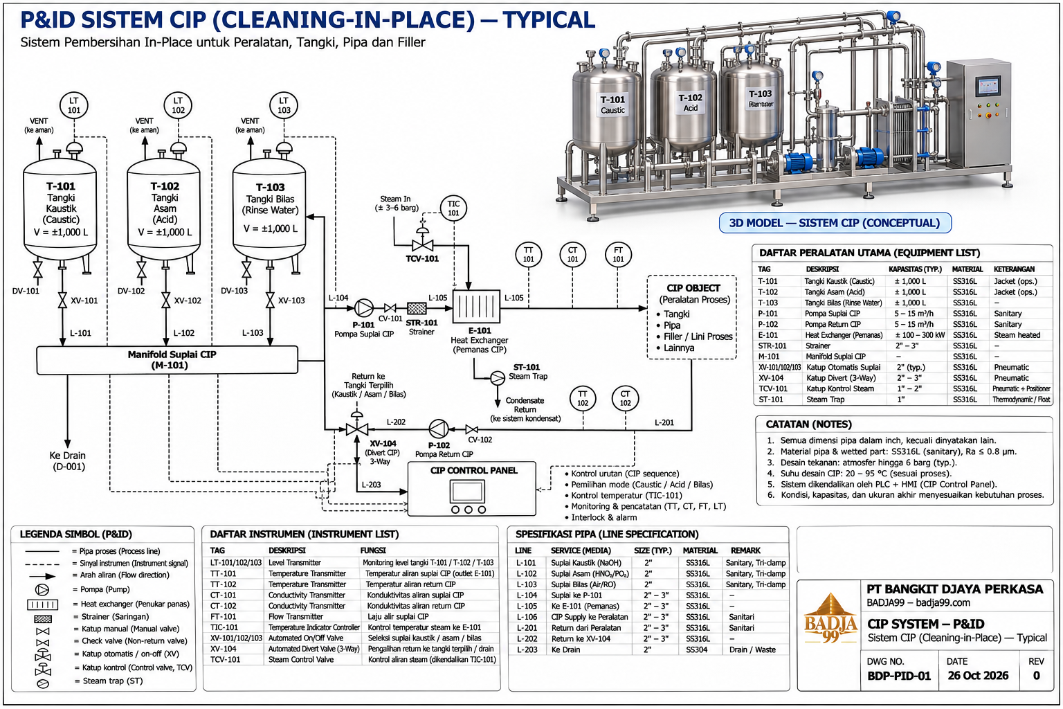
Solution tanks: hold cleaning solutions and rinse water according to the system configuration.
Supply and return pumps: circulate cleaning solutions to the equipment and return them to the tanks.
Heat exchanger: heats the cleaning solution and maintains the required process temperature.
Sensors and instrumentation: monitor parameters such as temperature, conductivity, and flow as required.
Automatic valves: direct cleaning solutions to the selected piping routes, tanks, or discharge lines.
Control panel, PLC, and HMI: execute cleaning sequences, manage process parameters, and display operating conditions. Data recording can be included where required.
Tank configuration, pump capacity, heating method, instrumentation, and automation level are determined by the requirements of each project.
Integration with Existing Production Lines
The CIP system must suit the layout of existing production lines and equipment. Design considerations include connections to product tanks and piping, separation between cleaning routes and production lines in use, and access for inspection and maintenance.
For operating facilities, installation activities can be coordinated with the plant team to help minimize disruption to production.
P&ID and System Configuration
A P&ID (Piping and Instrumentation Diagram) illustrates piping routes, tanks, pumps, valves, instrumentation, and flow direction within the CIP system. It helps define equipment relationships and serves as a reference for design and installation.
Depending on the application, the system may include solution tanks, supply and return pumps, heating equipment, sensors on relevant lines, and routing valves. The final configuration is determined by cleaning requirements, equipment characteristics, and plant conditions.